The (vehicle) speed signal of cars and light commercial vehicles has been one of the most important signals for aftermarket systems such as cruise controls, limiters, GPS navigation systems, taximeters and telematics that are installed after the vehicle has been registered. Many of those systems need that signal to function properly, despite the availability of good GPS. In this article we look at the development that the speed signal has undergone over the years, from pulse generator via API and CAN technology to the latest network protocols that we now face.
In the late 1980s, when sales of aftermarket cruise controls and fleet management systems for cars and light commercial vehicles started in the Netherlands, the demand for a good speed signal increased. And it even took off in the 1990s with the introduction of GPS navigation systems, which were not yet available as a stand-alone system (TomTom) or via an application such as Google Maps. However, the electronic speed signal that all those systems needed was not always available in the desired form in the vehicle, especially if it was an older car. Even if there was an electronic speed signal available, it wasn’t always suitable for the aftermarket system, tapping from it sometimes led to problems in the vehicle. This created a market for pulse generators, pulse dividers, pulse amplifiers and pulse interfaces.
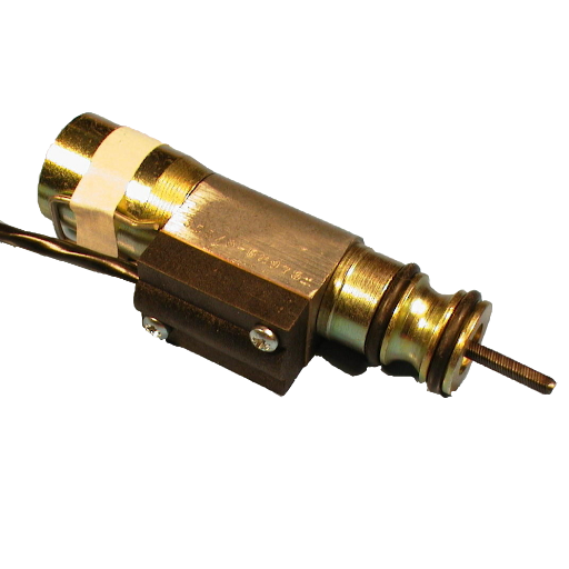
Until the 1980s, many cars and light commercial vehicles only had a mechanical speed signal. The speedometer was mechanically driven by a so-called odometer cable that connected the output shaft of the gearbox/differential to the speedometer. The odometer cable consisted of an outer and an inner cable. When the car started to move, the inner cable turned and the speedometer needle moved out. The speed of that inner cable increased directly proportional to an increase in vehicle speed. The faster the inner cable turned, the higher the speed indicated on the speedometer. Even today, there are still (older) vehicles on the road with this technology. If you need an electronic speed signal for a taximeter, for example, you can achieve this in two ways: with a pulse generator or with a magnetic sensor. Pulse generators, often of the Hall type, convert a mechanical rotating movement into an electronic pulse signal and are placed at one of the ends of the odometer cable. Magnetic sensors also convert a mechanical rotating movement into an electronic pulse signal, but they do this inductively (a coil in combination with magnets). They were placed near a drive shaft under the car. I deliberately say ‚were‘ because that location is very sensitive to disruptions.
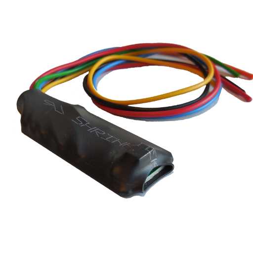
In the late 1990s, car manufacturers increasingly replaced the odometer cable with an electronic Hall transmitter, which resulted in a rapid increase in the share of cars with an electronic speed signal. You would think that would be great for the installers, but it soon became apparent that this signal was not always suitable for controlling an aftermarket system in addition to the car’s speedometer. It could happen that after the system was installed, the car’s speedometer malfunctioned or stopped working altogether. The aftermarket system could also have difficulty with the specifications of the original speed signal, causing it to not function properly. The call for a suitable adapter/interface increased rapidly, which actually led to the creation of the R&D department of Beijer Automotive. The Automatic Pulse Interface, or API for short, was rapidly developed there, which solved almost all speed signal problems. And has been doing so for over 20 years now. Nowadays, it is no longer used in the large numbers of those days, because developments in the automotive industry continued as usual and a new technology was already about to get under way: CAN.
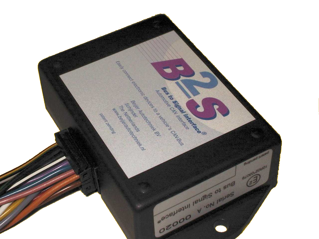
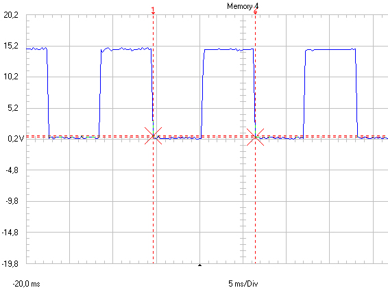
The CAN technology (Controller Area Network) developed by Bosch was first used in the Mercedes S-class (W140) that came onto the market in 1991. It was only a small network, also called a CAN bus, with limited functionalities that were also conventionally supported as a backup, such as the speed signal that was not only available on the digital CAN network but also analogue or ‚discrete‘ as it was also called. But developments went fast and soon afterwards cars appeared on the market where all important functions in the car were controlled via the CAN bus and signals were no longer always analogue. This applied to a speed signal, but also to lighting signals and even to a switched power supply that we had been used to branching off from the ignition switch since the 1950s. And so Beijer’s R&D engineers were able to get back to work to find a solution for all those installers of aftermarket systems who could no longer find their trusted analogue speed signal in those cars. Shortly afterwards, Beijer introduced the Bus-to-Signal interface (B2S). A CAN interface that, when connected to the correct location in the vehicle, recognized the CAN protocol, read the data on the CAN bus and translated this into reliable analogue signals, such as a speed signal. Because the B2S could only read the data on the CAN bus and not write it, malfunctions and error codes in the car were prevented. It was the solution that provided installers with hassle-free installation of aftermarket systems.
Over the years, the number of cars with CAN technology increased so much that the B2S reached the limits of its capabilities. Because the development of chips had also continued, it was time for a successor: the BCI. This all-rounder was first deployed around 2012-2013 and remains perhaps the most reliable CAN interface on the market to this day. One that is also regularly used for a second life as a refurbished BCI.
It is not without reason that the Netherlands Measurement Institute (NMi) – an independent specialist in testing, inspection, certification and training in metrology – uses BCI equipment for combination tests on automotive aftermarket equipment that places high demands on the accuracy of speed signals and reliability under extreme conditions.
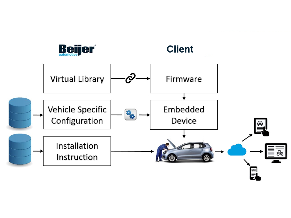
Because manufacturers of cars and light commercial vehicles, unlike truck manufacturers, always use their own CAN protocol and this can even vary per model, Beijer’s R&D department has built up an enormous database over the years – through countless measurements. That data is no longer only sold via interfaces, but also via a CAN library that is linked to the software of aftermarket system manufacturers. A digital ‚library‘ with car, motorcycle, light commercial vehicle, truck and agricultural vehicle data. The aftermarket system gains access via the Library to a large amount of vehicle data such as the speed signal, engine speed, lighting signals, but also data about the condition of the battery of an electric vehicle. The telematics, cruise control, limiter or other system to be installed can function smoothly without the intervention of an interface.
Meanwhile, in today’s modern cars, the CAN protocol is no longer the standard. That role has been taken over by faster and more advanced protocols such as FlexRay, CAN-FD and Ethernet. A development that was started years ago and has been closely monitored and implemented by the R&D of Beijer Automotive. We are once again ready for the future!