The speed signal in modern cars is increasingly generated by the ABS and subsequently passed to the CAN-bus, meaning that an immediately usable speed signal is often no longer available for use by such things as the navigation system, for example.
In some cases, the manufacturer of the ABS unit (e.g. Bosch or Até) has configured an open-collector output in the ABS controller. Sometimes this output is used by the car manufacturer and is also wired, but very often this output is not used and is not wired. Although this open-collector output generates a pulsing speed-dependent signal while the car is moving, this is not in the form of alternating voltages. The signal pulses by first hanging ‘free’ and then is grounded on the earth again. If you measure this in the normal way with an oscilloscope or multimeter (i.e. you measure the voltage difference between the signal and an earth point) you will not measure anything, because there are not alternating voltages across these points. However, if you measure the voltage difference between the signal and a supply, you will see that a pulse does indeed appear.
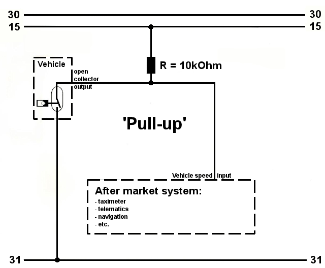 Once it has been determined that there is a pulsing open-collector output, the signal can be made suitable for such things as a navigation system by externally providing the system with a PULL-UP resistor.
See picture.
By connecting the signal via a 10k resistance to a 12 volt supply (PULL-UP), a voltage is applied to the wire by the resistor that sets the pulse ‘high’ at the moment that the wire is ‘free’. This gives rise to alternating voltages, creating a good analogue speed signal which can be used by many systems.